


STRUCTURAL ANALYSIS AND DESIGN
FOR SELF SUPPORTING TOWER
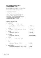
In compliance with the technical specification, the document describes
the minimum criteria for specifying and designing of tower.
I. STANDARD / REFERENCE
a. TIA / EIA - 222 - STANDARD : Structural Standards for Steel Antenna Towers and Antenna Supporting Structures.
b. AISC-ASD Code ' 89 - American Institute of Steel Construction
c. ACI 318-89 Code - American Concrete Institute
d. Indonesian Loading Code ( PMI 1970 N.I-I8 )
II. MATERIALS SPECIFICATION
a.Steel Structure
- Structure Type = Self Supporting Tower
- Steel Shapes & Plates = ASTM A 36 / JIS G3101
fy = 245 Mpa
b.Bolt & Nut
- Splice Bolts = ASTM A - 325 / JIS B1051 - Grade 8.8
fy = 560 Mpa
c.Anchor Bolt
- Grade of Anchor = ASTM A - 307
fy = 240 Mpa
d.First Coating
- Hot Dipped Galv. = ASTM A - 123
80 microns thickness
e.Concrete
- fc' = 19 Mpa ( 28 days ) / K-225
f.Rebars
- Grade of rebars = BJTP ( dia. ≤ 12 mm )
fy = 240 Mpa
- Grade of rebars = BJTD ( dia. ≥ 13 mm )
fy = 390 Mpa
g.Welding Electrodes
- Minimum Grade of Welding Electrode = AWS A5.1 E60XX.
fy = 345 Mpa
III. LOADINGS
a.Dead Load
Consist of Weight of Tower structure including antenna, ladder and appurtenances.
b.Wind Load
Calculated according to TIA / EIA - 222 - STANDARD : Structural Standard for Steel Antenna Towers and Antenna Supporting Structures
Maximum Wind Speed 120 Kph (3 Second Gust) and,Operational wind speed 84 Kph.
Where wind force applied to each section of the structure shall be calculated from the equation :
F = horizontal force applied to a section of the structure ( KN )
qz * GH * [ CF * AE + SCA*AA)], but not to exceed 2*qz*GH*AG
qz = Velocity pressure ( Pa )
= .613 Kz V2 for V in m/s
Kz = Exposure Coefficient
= [z/10]2/7 for z in meters
1.00 < Kz<2.58
V = basic wind speed for the structure location ( m.s-1)
z = height above average ground level to midpoint of panel of the structure and appurtenances ( M )
GH = gust response factor
CF = structure force coefficient
e = (AF+AR)/AG
e = solidity ratio
AF = projected area of flat structural component in one face of the section ( m2 )
AG = gross area of one tower face ( m2 )
AR = Projected area ( m2 ) of round structural component in one face of the section
AE = efective projected area of structural component in one face ( m2 )
= DF AF + DR AR RR (m2)
( Note : For tubular steel pole structure, AE shall be the actual projected area based on diameter or overall width. )
RR = .51e2 + .57 RR<1.0
RR = The reduction factor for round structural component
DF = Wind direction factor
1 for square cross section and normal wind direction
1+ 0.75 e for square cross section and + 450 wind direction (1.2 max)
DR = Wind direction factor for round structural components
= 1 ; for square cross section and normal wind direction
= 1+ 0.75 e ; for square cross section and + 450 wind direction (1.2 max)
CA = linear or discrete appurtance force coefficient
AA = projected area of a linear appurtance
CA is depended on Aspect ratio
Aspect Ratio = Overall length/width ratio in plane normal to wind direction
Wind Load Calculation method on the antennas is as follow:
Fa = Ca x A x Kz x GH x V2
Fs = Cs x A x Kz x GH x V2
M = Cm x D x A x Kz x GH x V2
Ha = (Fa2+Fs2 )1/2
Mt = Fa x X + Fs x Y + M
L = the distance the antenna's axis to the frame's joints
GH = Gust response factor from 2.3.4
= 0.65+0.6/(h/10)1/7 for h in meters
A = Outside aperture area of parabolic reflector, grid, or horn antenna
= Plate area of passive reflector ( ft2 )
D = Outside diameter of parabolic reflector, grid, or horn antenna ( ft )
= Width or length of passive reflector ( ft2 )
V = basic wind speed ( m.p.h ) from 2.3.3
KZ = Exposure coefficient from 2.3.3 with z equal to the hight
of the origin of the axis system
Kz = Exposure Coefficient
= [z/10]2/7 for z in meters
FA = axial force ( lb )
Fs = side force ( lb )
M = Twisting moment ( ft-lb )
Ca, Cs, Cm are load coeficients contained in tables B1
trough B6 as function of wind angle,…... TIA page 62-67
Ha = resultant of FA and FS ( lb )
Mt = Total twisting moment ( ft-lb )
X = The offset of the mounting pipe ( ft )
Y = The distance on the reflector axis from the reflector vertex to the center of the mounting pipe ( ft )
Wind Load Calculation methode on the parabolic antenna is as follow:
Fa = Ca x A x Kz x GH x V2
Fs = Cs x A x Kz x GH x V2
M = Cm x D x A x Kz x GH x V2
Ha = (Fa2+Fs2 )1/2
Mt = Fa x X + Fs x Y + M
where:
Fa = axial force ( kg )
Fs = side force ( kg )
M = Twisting moment ( kg-m )
Ca = Wind load coeficient
Cs = Wind load coeficient
Cm = Wind load coeficient
V = Wind velocity ( m.p.h )
c.Antennas Load and Top body part dimension.
Tower Structure considered to be able to support the antennas load
IV. LOAD COMBINATION
According to AISC - ASD'89 Standard , only the following load combination shall be investigated when calculating the maximum member stresses and structure reaction :
COMB 1 = DL
COMB 2 = DL + LL
COMB 3 = DL + LL ± WL
Where ;
DL : Dead Load
LL : Live Load
WL : Wind Load
V. DESIGN TOLERANCES
The design / analysis tolerances are :
a.Allowable Stress Ratio = 1
b.Slenderness Ratio :
Leg ≤ 150
Bracing ≤ 200
Redudant ≤ 250
c.Allowable Twist = 0.5 degree
d.Allowable Sway = 0.5 degree
e.Allowable Horizontal Displacement = H/200 ( H= Tower Height )
f.Verticality = H/2000 ( H= Tower Height )
VI. ALLOWABLE UNIT STRESS
The unit stresses in the stucture membersdo not aceed the allowable unit stresses for the materials as specified in the EIA standard EIA - 222
1. Tension
Ft = 0.60 Fy ( Kg/cm2 )
2. Shear
Fv = 0.40 Fy ( Kg/cm2 )
3. Compression
i ) On the gross section of axial loaded compression members when kl/r is less than Cc :
ii ) On the gross section of axial loaded compression member, when kl/r exceeds
4) Bending
Tension and compression on extreme fibers :
Fb = 0.66 Fy (Kg/cm2)
5) Tension on Bolts
Fv = 0.60 Fy ( kg/cm2 )
6) Shear on Bolts
Fv = 0.30 Fy ( kg/cm2 )
7) Bearing on Bolts
Fp = 1.20 Fv ( kg/cm2)
Untuk mendownload versi .pdf, silahkan anda klik link di bawah ini :
FOR SELF SUPPORTING TOWER
In compliance with the technical specification, the document describes
the minimum criteria for specifying and designing of tower.
I. STANDARD / REFERENCE
a. TIA / EIA - 222 - STANDARD : Structural Standards for Steel Antenna Towers and Antenna Supporting Structures.
b. AISC-ASD Code ' 89 - American Institute of Steel Construction
c. ACI 318-89 Code - American Concrete Institute
d. Indonesian Loading Code ( PMI 1970 N.I-I8 )
II. MATERIALS SPECIFICATION
a.Steel Structure
- Structure Type = Self Supporting Tower
- Steel Shapes & Plates = ASTM A 36 / JIS G3101
fy = 245 Mpa
b.Bolt & Nut
- Splice Bolts = ASTM A - 325 / JIS B1051 - Grade 8.8
fy = 560 Mpa
c.Anchor Bolt
- Grade of Anchor = ASTM A - 307
fy = 240 Mpa
d.First Coating
- Hot Dipped Galv. = ASTM A - 123
80 microns thickness
e.Concrete
- fc' = 19 Mpa ( 28 days ) / K-225
f.Rebars
- Grade of rebars = BJTP ( dia. ≤ 12 mm )
fy = 240 Mpa
- Grade of rebars = BJTD ( dia. ≥ 13 mm )
fy = 390 Mpa
g.Welding Electrodes
- Minimum Grade of Welding Electrode = AWS A5.1 E60XX.
fy = 345 Mpa
III. LOADINGS
a.Dead Load
Consist of Weight of Tower structure including antenna, ladder and appurtenances.
b.Wind Load
Calculated according to TIA / EIA - 222 - STANDARD : Structural Standard for Steel Antenna Towers and Antenna Supporting Structures
Maximum Wind Speed 120 Kph (3 Second Gust) and,Operational wind speed 84 Kph.
Where wind force applied to each section of the structure shall be calculated from the equation :
F = horizontal force applied to a section of the structure ( KN )
qz * GH * [ CF * AE + SCA*AA)], but not to exceed 2*qz*GH*AG
qz = Velocity pressure ( Pa )
= .613 Kz V2 for V in m/s
Kz = Exposure Coefficient
= [z/10]2/7 for z in meters
1.00 < Kz<2.58
V = basic wind speed for the structure location ( m.s-1)
z = height above average ground level to midpoint of panel of the structure and appurtenances ( M )
GH = gust response factor
CF = structure force coefficient
e = (AF+AR)/AG
e = solidity ratio
AF = projected area of flat structural component in one face of the section ( m2 )
AG = gross area of one tower face ( m2 )
AR = Projected area ( m2 ) of round structural component in one face of the section
AE = efective projected area of structural component in one face ( m2 )
= DF AF + DR AR RR (m2)
( Note : For tubular steel pole structure, AE shall be the actual projected area based on diameter or overall width. )
RR = .51e2 + .57 RR<1.0
RR = The reduction factor for round structural component
DF = Wind direction factor
1 for square cross section and normal wind direction
1+ 0.75 e for square cross section and + 450 wind direction (1.2 max)
DR = Wind direction factor for round structural components
= 1 ; for square cross section and normal wind direction
= 1+ 0.75 e ; for square cross section and + 450 wind direction (1.2 max)
CA = linear or discrete appurtance force coefficient
AA = projected area of a linear appurtance
CA is depended on Aspect ratio
Aspect Ratio = Overall length/width ratio in plane normal to wind direction
Wind Load Calculation method on the antennas is as follow:
Fa = Ca x A x Kz x GH x V2
Fs = Cs x A x Kz x GH x V2
M = Cm x D x A x Kz x GH x V2
Ha = (Fa2+Fs2 )1/2
Mt = Fa x X + Fs x Y + M
L = the distance the antenna's axis to the frame's joints
GH = Gust response factor from 2.3.4
= 0.65+0.6/(h/10)1/7 for h in meters
A = Outside aperture area of parabolic reflector, grid, or horn antenna
= Plate area of passive reflector ( ft2 )
D = Outside diameter of parabolic reflector, grid, or horn antenna ( ft )
= Width or length of passive reflector ( ft2 )
V = basic wind speed ( m.p.h ) from 2.3.3
KZ = Exposure coefficient from 2.3.3 with z equal to the hight
of the origin of the axis system
Kz = Exposure Coefficient
= [z/10]2/7 for z in meters
FA = axial force ( lb )
Fs = side force ( lb )
M = Twisting moment ( ft-lb )
Ca, Cs, Cm are load coeficients contained in tables B1
trough B6 as function of wind angle,…... TIA page 62-67
Ha = resultant of FA and FS ( lb )
Mt = Total twisting moment ( ft-lb )
X = The offset of the mounting pipe ( ft )
Y = The distance on the reflector axis from the reflector vertex to the center of the mounting pipe ( ft )
Wind Load Calculation methode on the parabolic antenna is as follow:
Fa = Ca x A x Kz x GH x V2
Fs = Cs x A x Kz x GH x V2
M = Cm x D x A x Kz x GH x V2
Ha = (Fa2+Fs2 )1/2
Mt = Fa x X + Fs x Y + M
where:
Fa = axial force ( kg )
Fs = side force ( kg )
M = Twisting moment ( kg-m )
Ca = Wind load coeficient
Cs = Wind load coeficient
Cm = Wind load coeficient
V = Wind velocity ( m.p.h )
c.Antennas Load and Top body part dimension.
Tower Structure considered to be able to support the antennas load
IV. LOAD COMBINATION
According to AISC - ASD'89 Standard , only the following load combination shall be investigated when calculating the maximum member stresses and structure reaction :
COMB 1 = DL
COMB 2 = DL + LL
COMB 3 = DL + LL ± WL
Where ;
DL : Dead Load
LL : Live Load
WL : Wind Load
V. DESIGN TOLERANCES
The design / analysis tolerances are :
a.Allowable Stress Ratio = 1
b.Slenderness Ratio :
Leg ≤ 150
Bracing ≤ 200
Redudant ≤ 250
c.Allowable Twist = 0.5 degree
d.Allowable Sway = 0.5 degree
e.Allowable Horizontal Displacement = H/200 ( H= Tower Height )
f.Verticality = H/2000 ( H= Tower Height )
VI. ALLOWABLE UNIT STRESS
The unit stresses in the stucture membersdo not aceed the allowable unit stresses for the materials as specified in the EIA standard EIA - 222
1. Tension
Ft = 0.60 Fy ( Kg/cm2 )
2. Shear
Fv = 0.40 Fy ( Kg/cm2 )
3. Compression
i ) On the gross section of axial loaded compression members when kl/r is less than Cc :
ii ) On the gross section of axial loaded compression member, when kl/r exceeds
4) Bending
Tension and compression on extreme fibers :
Fb = 0.66 Fy (Kg/cm2)
5) Tension on Bolts
Fv = 0.60 Fy ( kg/cm2 )
6) Shear on Bolts
Fv = 0.30 Fy ( kg/cm2 )
7) Bearing on Bolts
Fp = 1.20 Fv ( kg/cm2)
Untuk mendownload versi .pdf, silahkan anda klik link di bawah ini :


Jemi
BalasHapusThanks, I will review and comment
Ok,Thank U. I'm waiting your response.
BalasHapusHi..jemi, How could it be implemented using PLS-TOWER computer software. thx
BalasHapusmas jemmy, klo mau analisis self supporting tower buat di pakai sebagai tower wind mills bisa?
BalasHapusmisal dengan tinggi 15 m
makasih
Maksud tower wind mills utk jenis apa ya,.Tower ini utk jenis rangka..
BalasHapusMas Jemi,
BalasHapusAngka Max wind speed 120 kph itu dapat darimana ya? kita tentukan sendiri berdasarkan data kec. angin perlokasi/site atau memang ada di TIA/EIA? kalau memang ada dibagian mananya ya mas?
Kalau yang Operational wind yang 84 kph saya lihat memang di TIA/EIA ada di Operational Requirements yaitu setara dgn 22.4m/s. Mohon pencerahannya.
Thanks B4.
Salam,.
BalasHapusPrinsipnya basic Wind speed/Load tergantung requirement dan akan berbeda disetiap lokasi/negara (menurut TIA/EIA and Code lain normalnya rencana design Wind speed 50 tahunan. Tp utk di Indonesia biasanya Wind speed 120 kph (fastest mile) sdh sgt cukup. Tetapi sebagian operator/owner sekarang menggunakan 120 kph (3 second gust). Sebenarnya ini salah kaprah dimana masih byk designer dg Ms.Tower versi 6.01 (TIA/EIA-222F) menggunakan istilah 3 second gust, yang mana hanya bisa digunakan pada Ms.Tower 6.02 (TIA/EIA-222G update)..Hanya dengan alasan konversi designer tsb men-change fastest mile ke 3 second gust. Padahal versi F dg G sdh berbeda baik metoda analisanya (ASD ke LRFD), Terrain factor, Load kombinasi dll..
Semoga bermanfaat.
Mas Jemi,
BalasHapusThanks untuk penjelasannya, sangat informatif. kalau bisa saya simpulkan kec. angin 120 kph hanya asumsi/common practice designer tower di Indonesia yang mengikuti design criteria terdahulu/pendahulunya?(misalkan karena telkom sudah menentukan asumsi design criteria tower diawal spt itu, untuk selanjutnya operator lain/designer tower mengikuti parameter tsb.
Mungkin okelah bisa kita tetapkan fastest mile 120 kph sehingga bisa dianggap sudah sangat cukup..tapi dasarnya apa? dan mengacu kemana? apakah data BMG? seperti data curah hujan tahunan atau klasifikasi daerah gempa atau Indonesia punya windspeed map yang dikeluarkan secara formal oleh lembaga yang berwenang seperti pada IBC section 1609. Karena kaitannya secara ekonomi/berat tower mungkin akan berbeda cukup signifikan bila kita tidak tepat menetapkan nilai fastest mile ini. dan tugas sebagai seorang designer untuk menetapkan design yang paling optimum dengan parameter yang tepat bukan? Nah 120 kph ini merupakan parameter yg tepat atau tidak? misalkan berdasarkan data yg dikeluarkan BMG No.sekian tahun sekian tercatat angin tercepat yang pernah terjadi pada 50 thn terakhir di Indonesia adalah 120 kph di daerah NTT...mohon masukannya mas. Terimakasih banyak.
Sudah saya sebutkan sebelumnya bahwa design rencana utk Wind Speed normalnya pakai standard data 50 tahunan. Tp ada juga yang 100 thnan..Byk acuannya, TIA/EIA, ASCE and BS code menyatakan standard 50 thn (Itu klo mengacu CODE yg ada). Tp kita (Owner ato Designer) bisa menentukan sendiri Wind rencana tsb bs lebih rendah berdasar (faktor keutamaan strukture dan ekonomis). Misalnya utk tower Radio PRIBADI dan lokasi jauh dari pemukiman bisa saja kita menggunakan Wind speed rencana 10 tahunan..Semoga bermanfaat.
BalasHapussaya mau tanya kalau structural bolt m29,heavy hex head 70 mm legth,ASTM A325 Nama lainnya apa ya? tau persamaan dengan apa?tolong dibantu.terima kasih
BalasHapusmoncler
BalasHapusgolden goose sneakers
yeezy
bape
golden goose sneakers
kd 12
michael jordan shoes
jordan sneakers
longchamp handbags
golden goose
find replica ysl bags straight from the source replica bags additional hints replica ysl handbags
BalasHapus