Design and Fabrication Drawing S/S Tower 12.5m Roof Top

Tower roof top for radar and investigation "Sing Airport".

Design and Fabrication Drawing S/S Tower 27.75m Roof Top

Tower roof top for radar and investigation "Sing Airport".

Tower Broadcast TVRI Jogja

Site survey, checking and recalculation for strengthening.

Broadcast Tower

Broadcast Tower
SURVEY & Reanalysis TVRI JOGJA 100m

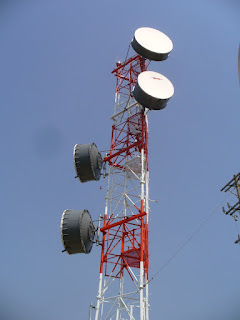
TelecommunicationTower

TelecommunicationTower
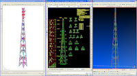
Desidn & Fabrication DRAWING SST-27.75m

Tower Roof Top

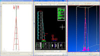
Tower Roof Top
Design & Fabrication DRAWING SST-12.5m

Kamis, 16 Juli 2009

Ms Tower V 6.01

Analysis and Checking of Latticed Towers & Masts


MStower V6 is a Windows program for the analysis and checking of latticed towers and masts. It is used by designers and authorities for the checking of transmission line structures and communications towers and masts.


RENDERED PLOT OF PART OF A TOWER

MStower V6 is a Windows program for the analysis and checking of latticed towers and masts. It is used by designers and authorities for the checking of transmission line structures and communications towers and masts.
The program has options for the generation of geometry and loading, analysis, application of gust factors to member forces, and checking of members. There are comprehensive facilities for plotting of the structure, loading, and results. The structure geometry is specified by data describing panels, dimensions, sections, and ancillary equipment. Section properties and ancillary data are taken from standard library files. Wind and ice loads on members, antennas, and ancillaries are computed automatically.
Loads may be computed according to the rules of:
  • BS 8100:Part 1:1986 (towers)
  • BS8100:Part 4:1995 (guyed masts)
  • ANSI EIA/TIA-222-F-1996
  • AS3995-1994
  • Malaysian Electricity Supply Regulations 1990
Alternatively, any user-defined wind velocity profile may be used. Patch loading may be computed for masts.
Ancillaries are shown on the screen and each may be interrogated by clicking on it.


PLOT OF PART OF TOWER WITH ANTENNAS

Member forces are extracted directly from the analysis results. Non-linear analysis is used for masts and a catenary cable element is used for the guys.
Tower members may be checked using the rules of:
  • BS8100:Part 3:1997 (Limit state)
  • BS449:1990 (Allowable stress)
  • AS 3995-1994 (Limit state)
  • ANSI 10-90 (Limit state)
  • EIA/TIA-222-F. 1996 (Allowable stress)
Analysis results and member check results may be displayed graphically and reports may be displayed and printed as required. An important application of MStower is the reassessment of existing structures subjected to modified loading. For example, increased loading may result from the installation of additional ancillary equipment or conductors. MStower is also useful for checking serviceability requirements. A special report gives both tower reactions and angular displacements of ancillaries under wind loading.

Please have the original Software.
Posted from : www.mstower.com

Senin, 13 Juli 2009

Basic Design and Construction aspects of Transmission Lines


1 INTRODUCTION 1.1 What is Transmission line?

This question can simply not be answered by a few words. Each chapter in this lecture notes probably will use to give a proper answer of it.

A transmission line is a device for the transfer of electric energy. It can transfer the energy over long or short distances, and at different voltages. Transfer of electrical energy over very long distances calls for a trunk line with high voltages. The transmission lines of very high voltages, such as; 70 kV, 150 kV, 220 kV, 400 kV, are part of a national grid (GRT in Belgium). To make it easier to understand it can be said that the transmission lines with the higher voltages are the highways in the energy transfer system. In between these highways and the small “paths”, which might call distribution network to drop the voltage line from higher level to lower level, there will be a lot of transmission lines with different voltages.

In the planning and design of transmission line, a number of requirements have to be met. From the electrical point of view, the most important requirement is insulation and safe clearances to earthed parts. These, together with the cross-section of conductors, the spacing between conductors, and the relative location of ground wires with respect to the conductors, influence the design of pylons and foundations.

"lanjutan postingan"

Rabu, 08 April 2009

Company Profile

Kami adalah tenaga-tenaga outsourcing profesional yang berpengalaman dibidangnya dalam menyediakan jasa Consulting, Engineering dan Construction dengan produk dan service :


Analysis Design & Fabrictaion Drawings :
• Site acquisition (S1TAC)
• Telecommunication Tower
• Strengthening Tower  (Re-analysis Existing)
• Mechanical/Electrical
• Accessories
• Maintenance


General Steel Structure Design & Fabrication Drawings :
• High Voltage Transmission Lines Tower PLN
• Bridge
• Steel Truss
• Steel Structure or Building
• BillBoard
• Design Foundation


Detailing & Construction Drawing Services
• Steel Structure Telecommunication Tower
• High Voltage Transmission Lines Tower
• Bridge
• Steel Structure or Building
• Steel Truss


Engineering Service
• Design consultant
• Construction Management


Kamis, 12 Maret 2009

Tower Sharing Telekomunikasi

Dear All,.


Saya sangat berminat kepada para corespondence yang ingin menambah wawasan tentang study analisa tower telekomunikasi dan transsmissi ataupun untuk reanalysis perkuatan tower. Dan saya berharap dalam forum ini bisa mendapatkan banyak corespondence yang mau berbagi atau sharing tentang dunia civil engineer khususnya bidang sower structures.

Hal yang paling hot dibicarakan di dunia telekomunikasi saat ini adalah semakin menjamurnya tower tower baru yang sangat merusak pemandangan terutama di wilayah perkotaan. Oleh karena itu sangat perlu dibuatkan solusi untuk mengatasi masalah "jamur-jamur tersebut". Sekarang pemerintah telah mulai bertindak protective terhadap wilayahnya dari pembangunan menara BTS tersebut. Berbagai inisiatif telah dikemukakan baik dari kalangan akademis muapun dari para instansi yang bergerak dalam dunia ini misalnya para perencana atau designer struktur tower. Perlunya tower tower sharing untuk multi-operator sekarang sudah mulai dikembangkan. Terutama sistem colocation yaitu penggunaan tower existing suatu operator untuk bisa digunakan oleh beberapa operator lain. Dan hal ini telah mulai dikembangkan oleh para provider dan vendor telekomunikasi.

Perencanaan steel antenna tower sangat penting dan banyak dijumpai pada saat ini. Hal ini akibat semakin berkembang pesatnya teknologi komunikasi, sebagai contoh karena semakin banyaknya pengguna layanan komunikasi mobile phone dengan teknologi CDMA maupun GSM. Oleh karena itu pihak pengembang teknologi tersebut banyak membangun maupun merencanakan ulang tower untuk memperluas jaringan atau sinyal komunikasi. Perencanaan ulang tower yang sudah ada dilakukan untuk meningkatkan kapasitas beban antena, sehingga jaringan sinyal dapat menjangkau area yang lebih luas.

Pada perencanaan tower, beban lateral yang berpengaruh secara dominan adalah beban angin, karena pengaruh perbandingan antara ketinggian dan lebar struktur yang sangat besar (langsing). Tujuannya adalah melakukan analisa ulang kekuatan pada steel antenna tower akibat adanya penambahan beban antena. Beban angin diperhitungkan berdasarkan peraturan EIA Standard Structural Standards for Steel Antenna Tower and Antenna Supporting Structure [TIA/EIA-222-F/G, 1996], perencanaan perkuatan tower di Indonesia lazimnya dilakukan dengan bantuan software Ms.Tower versi 6 dimana program ini sudah diakui oleh para praktisi dibidang ini.

Design Criteria Tower

STRUCTURAL ANALYSIS AND DESIGN
FOR SELF SUPPORTING TOWER


In compliance with the technical specification, the document describes
the minimum criteria for specifying and designing of tower.

I. STANDARD / REFERENCE

a. TIA / EIA - 222 - STANDARD : Structural Standards for Steel Antenna Towers and Antenna Supporting Structures.
b. AISC-ASD Code ' 89 - American Institute of Steel Construction
c. ACI 318-89 Code - American Concrete Institute
d. Indonesian Loading Code ( PMI 1970 N.I-I8 )

II. MATERIALS SPECIFICATION

a.Steel Structure
- Structure Type = Self Supporting Tower
- Steel Shapes & Plates = ASTM A 36 / JIS G3101
fy = 245 Mpa
b.Bolt & Nut
- Splice Bolts = ASTM A - 325 / JIS B1051 - Grade 8.8
fy = 560 Mpa
c.Anchor Bolt
- Grade of Anchor = ASTM A - 307
fy = 240 Mpa
d.First Coating
- Hot Dipped Galv. = ASTM A - 123
80 microns thickness
e.Concrete
- fc' = 19 Mpa ( 28 days ) / K-225
f.Rebars
- Grade of rebars = BJTP ( dia. ≤ 12 mm )
fy = 240 Mpa
- Grade of rebars = BJTD ( dia. ≥ 13 mm )
fy = 390 Mpa
g.Welding Electrodes
- Minimum Grade of Welding Electrode = AWS A5.1 E60XX.
fy = 345 Mpa


III. LOADINGS

a.Dead Load
Consist of Weight of Tower structure including antenna, ladder and appurtenances.
b.Wind Load
Calculated according to TIA / EIA - 222 - STANDARD : Structural Standard for Steel Antenna Towers and Antenna Supporting Structures
Maximum Wind Speed 120 Kph (3 Second Gust) and,Operational wind speed 84 Kph.
Where wind force applied to each section of the structure shall be calculated from the equation :
F = horizontal force applied to a section of the structure ( KN )
qz * GH * [ CF * AE + SCA*AA)], but not to exceed 2*qz*GH*AG
qz = Velocity pressure ( Pa )
= .613 Kz V2 for V in m/s
Kz = Exposure Coefficient
= [z/10]2/7 for z in meters
1.00 < Kz<2.58
V = basic wind speed for the structure location ( m.s-1)
z = height above average ground level to midpoint of panel of the structure and appurtenances ( M )
GH = gust response factor
CF = structure force coefficient
e = (AF+AR)/AG
e = solidity ratio
AF = projected area of flat structural component in one face of the section ( m2 )
AG = gross area of one tower face ( m2 )
AR = Projected area ( m2 ) of round structural component in one face of the section
AE = efective projected area of structural component in one face ( m2 )
= DF AF + DR AR RR (m2)
( Note : For tubular steel pole structure, AE shall be the actual projected area based on diameter or overall width. )
RR = .51e2 + .57 RR<1.0
RR = The reduction factor for round structural component
DF = Wind direction factor
1 for square cross section and normal wind direction
1+ 0.75 e for square cross section and + 450 wind direction (1.2 max)
DR = Wind direction factor for round structural components
= 1 ; for square cross section and normal wind direction
= 1+ 0.75 e ; for square cross section and + 450 wind direction (1.2 max)
CA = linear or discrete appurtance force coefficient
AA = projected area of a linear appurtance
CA is depended on Aspect ratio
Aspect Ratio = Overall length/width ratio in plane normal to wind direction
Wind Load Calculation method on the antennas is as follow:
Fa = Ca x A x Kz x GH x V2
Fs = Cs x A x Kz x GH x V2
M = Cm x D x A x Kz x GH x V2
Ha = (Fa2+Fs2 )1/2
Mt = Fa x X + Fs x Y + M
L = the distance the antenna's axis to the frame's joints
GH = Gust response factor from 2.3.4
= 0.65+0.6/(h/10)1/7 for h in meters
A = Outside aperture area of parabolic reflector, grid, or horn antenna
= Plate area of passive reflector ( ft2 )
D = Outside diameter of parabolic reflector, grid, or horn antenna ( ft )
= Width or length of passive reflector ( ft2 )
V = basic wind speed ( m.p.h ) from 2.3.3
KZ = Exposure coefficient from 2.3.3 with z equal to the hight
of the origin of the axis system
Kz = Exposure Coefficient
= [z/10]2/7 for z in meters
FA = axial force ( lb )
Fs = side force ( lb )
M = Twisting moment ( ft-lb )
Ca, Cs, Cm are load coeficients contained in tables B1
trough B6 as function of wind angle,…... TIA page 62-67
Ha = resultant of FA and FS ( lb )
Mt = Total twisting moment ( ft-lb )
X = The offset of the mounting pipe ( ft )
Y = The distance on the reflector axis from the reflector vertex to the center of the mounting pipe ( ft )
Wind Load Calculation methode on the parabolic antenna is as follow:
Fa = Ca x A x Kz x GH x V2
Fs = Cs x A x Kz x GH x V2
M = Cm x D x A x Kz x GH x V2
Ha = (Fa2+Fs2 )1/2
Mt = Fa x X + Fs x Y + M

where:
Fa = axial force ( kg )
Fs = side force ( kg )
M = Twisting moment ( kg-m )
Ca = Wind load coeficient
Cs = Wind load coeficient
Cm = Wind load coeficient
V = Wind velocity ( m.p.h )

c.Antennas Load and Top body part dimension.
Tower Structure considered to be able to support the antennas load

IV. LOAD COMBINATION
According to AISC - ASD'89 Standard , only the following load combination shall be investigated when calculating the maximum member stresses and structure reaction :
COMB 1 = DL
COMB 2 = DL + LL
COMB 3 = DL + LL ± WL

Where ;
DL : Dead Load
LL : Live Load
WL : Wind Load

V. DESIGN TOLERANCES

The design / analysis tolerances are :
a.Allowable Stress Ratio = 1
b.Slenderness Ratio :
Leg ≤ 150
Bracing ≤ 200
Redudant ≤ 250
c.Allowable Twist = 0.5 degree
d.Allowable Sway = 0.5 degree
e.Allowable Horizontal Displacement = H/200 ( H= Tower Height )
f.Verticality = H/2000 ( H= Tower Height )


VI. ALLOWABLE UNIT STRESS
The unit stresses in the stucture membersdo not aceed the allowable unit stresses for the materials as specified in the EIA standard EIA - 222

1. Tension
Ft = 0.60 Fy ( Kg/cm2 )
2. Shear
Fv = 0.40 Fy ( Kg/cm2 )
3. Compression
i ) On the gross section of axial loaded compression members when kl/r is less than Cc :

ii ) On the gross section of axial loaded compression member, when kl/r exceeds

4) Bending
Tension and compression on extreme fibers :
Fb = 0.66 Fy (Kg/cm2)
5) Tension on Bolts
Fv = 0.60 Fy ( kg/cm2 )
6) Shear on Bolts
Fv = 0.30 Fy ( kg/cm2 )
7) Bearing on Bolts
Fp = 1.20 Fv ( kg/cm2)


Untuk mendownload versi .pdf, silahkan anda klik link di bawah ini :

Selasa, 10 Maret 2009

Analisa Perkuatan Tower Telekomunikasi


Dear All,.

Saya sangat berminat kepada para corespondence yang ingin menambah wawasan tentang study analisa tower telekomunikasi dan transsmissi ataupun untuk reanalysis perkuatan tower. Dan saya berharap dalam forum ini bisa mendapatkan banyak corespondence yang mau berbagi atau sharing tentang dunia civil engineer khususnya bidang sower structures.

Hal yang paling hot dibicarakan di dunia telekomunikasi saat ini adalah semakin menjamurnya tower tower baru yang sangat merusak pemandangan terutama di wilayah perkotaan. Oleh karena itu sangat perlu dibuatkan solusi untuk mengatasi masalah "jamur-jamur tersebut". Sekarang pemerintah telah mulai bertindak protective terhadap wilayahnya dari pembangunan menara BTS tersebut. Berbagai inisiatif telah dikemukakan baik dari kalangan akademis muapun dari para instansi yang bergerak dalam dunia ini misalnya para perencana atau designer struktur tower. Perlunya tower tower sharing untuk multi-operator sekarang sudah mulai dikembangkan. Terutama sistem colocation yaitu penggunaan tower existing suatu operator untuk bisa digunakan oleh beberapa operator lain. Dan hal ini telah mulai dikembangkan oleh para provider dan vendor telekomunikasi.

Perencanaan steel antenna tower sangat penting dan banyak dijumpai pada saat ini. Hal ini akibat semakin berkembang pesatnya teknologi komunikasi, sebagai contoh karena semakin banyaknya pengguna layanan komunikasi mobile phone dengan teknologi CDMA maupun GSM. Oleh karena itu pihak pengembang teknologi tersebut banyak membangun maupun merencanakan ulang tower untuk memperluas jaringan atau sinyal komunikasi. Perencanaan ulang tower yang sudah ada dilakukan untuk meningkatkan kapasitas beban antena, sehingga jaringan sinyal dapat menjangkau area yang lebih luas.

Pada perencanaan tower, beban lateral yang berpengaruh secara dominan adalah beban angin, karena pengaruh perbandingan antara ketinggian dan lebar struktur yang sangat besar (langsing). Tujuannya adalah melakukan analisa ulang kekuatan pada steel antenna tower akibat adanya penambahan beban antena. Beban angin diperhitungkan berdasarkan peraturan EIA Standard Structural Standards for Steel Antenna Tower and Antenna Supporting Structure [TIA/EIA-222-F/G, 1996], perencanaan perkuatan tower di Indonesia lazimnya dilakukan dengan bantuan software Ms.Tower versi 6 dimana program ini sudah diakui oleh para praktisi dibidang ini.


BR//JMI
(jemi_astomo@yahoo.com)

My Pictures