STRUCTURAL ANALYSIS AND DESIGN
FOR SELF SUPPORTING TOWER
In compliance with the technical specification, the document describes
the minimum criteria for specifying and designing of tower.
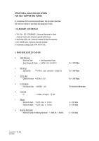
I. STANDARD / REFERENCE
a. TIA / EIA - 222 - STANDARD : Structural Standards for Steel Antenna Towers and Antenna Supporting Structures.
b. AISC-ASD Code ' 89 - American Institute of Steel Construction
c. ACI 318-89 Code - American Concrete Institute
d. Indonesian Loading Code ( PMI 1970 N.I-I8 )
II. MATERIALS SPECIFICATION
a.Steel Structure
- Structure Type = Self Supporting Tower
- Steel Shapes & Plates = ASTM A 36 / JIS G3101
fy = 245 Mpa
b.Bolt & Nut
- Splice Bolts = ASTM A - 325 / JIS B1051 - Grade 8.8
fy = 560 Mpa
c.Anchor Bolt
- Grade of Anchor = ASTM A - 307
fy = 240 Mpa
d.First Coating
- Hot Dipped Galv. = ASTM A - 123
80 microns thickness
e.Concrete
- fc' = 19 Mpa ( 28 days ) / K-225
f.Rebars
- Grade of rebars = BJTP ( dia. ≤ 12 mm )
fy = 240 Mpa
- Grade of rebars = BJTD ( dia. ≥ 13 mm )
fy = 390 Mpa
g.Welding Electrodes
- Minimum Grade of Welding Electrode = AWS A5.1 E60XX.
fy = 345 Mpa
III. LOADINGS
a.Dead Load
Consist of
Weight of Tower structure including antenna, ladder and appurtenances.
b.Wind Load
Calculated according to TIA / EIA - 222 - STANDARD : Structural Standard for Steel Antenna Towers and Antenna Supporting Structures
Maximum Wind Speed 120 Kph (3 Second Gust) and,Operational wind speed 84 Kph.
Where wind force applied to each section of the structure shall be calculated from the equation :
F = horizontal force applied to a section of the structure ( KN )
qz * GH * [ CF * AE + SCA*AA)], but not to exceed 2*qz*GH*AG
qz = Velocity pressure ( Pa )
= .613 Kz V2 for V in m/s
Kz = Exposure Coefficient
= [z/10]2/7 for z in meters
1.00 < Kz<2.58
V = basic wind speed for the structure location ( m.s-1)
z = height above average ground level to midpoint of panel of the structure and appurtenances ( M )
GH = gust response factor
CF = structure force coefficient
e = (AF+AR)/AG
e = solidity ratio
AF = projected area of flat structural component in one face of the section ( m2 )
AG = gross area of one tower face ( m2 )
AR = Projected area ( m2 ) of round structural component in one face of the section
AE = efective projected area of structural component in one face ( m2 )
= DF AF + DR AR RR (m2)
( Note : For tubular steel pole structure, AE shall be the actual projected area based on diameter or overall width. )
RR = .51e2 + .57 RR<1.0
RR = The reduction factor for round structural component
DF = Wind direction factor
1 for square cross section and normal wind direction
1+ 0.75 e for square cross section and + 450 wind direction (1.2 max)
DR = Wind direction factor for round structural components
= 1 ; for square cross section and normal wind direction
= 1+ 0.75 e ; for square cross section and + 450 wind direction (1.2 max)
CA = linear or discrete appurtance force coefficient
AA = projected area of a linear appurtance
CA is depended on Aspect ratio
Aspect Ratio = Overall length/width ratio in plane normal to wind direction
Wind Load Calculation method on the antennas is as follow:
Fa = Ca x A x Kz x GH x V2
Fs = Cs x A x Kz x GH x V2
M = Cm x D x A x Kz x GH x V2
Ha = (Fa2+Fs2 )1/2
Mt = Fa x X + Fs x Y + M
L = the distance the antenna's axis to the frame's joints
GH = Gust response factor from 2.3.4
= 0.65+0.6/(h/10)1/7 for h in meters
A = Outside aperture area of parabolic reflector, grid, or horn antenna
= Plate area of passive reflector ( ft2 )
D = Outside diameter of parabolic reflector, grid, or horn antenna ( ft )
= Width or length of passive reflector ( ft2 )
V = basic wind speed ( m.p.h ) from 2.3.3
KZ = Exposure coefficient from 2.3.3 with z equal to the hight
of the origin of the axis system
Kz = Exposure Coefficient
= [z/10]2/7 for z in meters
FA = axial force ( lb )
Fs = side force ( lb )
M = Twisting moment ( ft-lb )
Ca, Cs, Cm are load coeficients contained in tables B1
trough B6 as function of wind angle,…... TIA page 62-67
Ha = resultant of FA and FS ( lb )
Mt = Total twisting moment ( ft-lb )
X = The offset of the mounting pipe ( ft )
Y = The distance on the reflector axis from the reflector vertex to the center of the mounting pipe ( ft )
Wind Load Calculation methode on the parabolic antenna is as follow:
Fa = Ca x A x Kz x GH x V2
Fs = Cs x A x Kz x GH x V2
M = Cm x D x A x Kz x GH x V2
Ha = (Fa2+Fs2 )1/2
Mt = Fa x X + Fs x Y + M
where:
Fa = axial force ( kg )
Fs = side force ( kg )
M = Twisting moment ( kg-m )
Ca = Wind load coeficient
Cs = Wind load coeficient
Cm = Wind load coeficient
V = Wind velocity ( m.p.h )
c.Antennas Load and Top body part dimension.
Tower Structure considered to be able to support the antennas load
IV. LOAD COMBINATION
According to AISC - ASD'89 Standard , only the following load combination shall be investigated when calculating the maximum member stresses and structure reaction :
COMB 1 = DL
COMB 2 = DL + LL
COMB 3 = DL + LL ± WL
Where ;
DL : Dead Load
LL : Live Load
WL : Wind Load
V. DESIGN TOLERANCES
The design / analysis tolerances are :
a.Allowable Stress Ratio = 1
b.Slenderness Ratio :
Leg ≤ 150
Bracing ≤ 200
Redudant ≤ 250
c.Allowable Twist = 0.5 degree
d.Allowable Sway = 0.5 degree
e.Allowable Horizontal Displacement = H/200 ( H= Tower Height )
f.Verticality = H/2000 ( H= Tower Height )
VI. ALLOWABLE UNIT STRESS
The unit stresses in the stucture membersdo not aceed the allowable unit stresses for the materials as specified in the EIA standard EIA - 222
1. Tension
Ft = 0.60 Fy ( Kg/cm2 )
2. Shear
Fv = 0.40 Fy ( Kg/cm2 )
3. Compression
i ) On the gross section of axial loaded compression members when kl/r is less than Cc :
ii ) On the gross section of axial loaded compression member, when kl/r exceeds
4) Bending
Tension and compression on extreme fibers :
Fb = 0.66 Fy (Kg/cm2)
5) Tension on Bolts
Fv = 0.60 Fy ( kg/cm2 )
6) Shear on Bolts
Fv = 0.30 Fy ( kg/cm2 )
7) Bearing on Bolts
Fp = 1.20 Fv ( kg/cm2)Untuk mendownload versi .pdf, silahkan anda klik link di bawah ini :


 Dear All,.


